Voltage drop across resistors
One of the ways to step down a circuit tension is using resistors and obtain a voltage drop between those resistors. The technique is pretty forward: in a circuit with a given tension the tension is chopped inversely proportional across the resistors sections depending on each resistor value. This means that a section with a higher resistor value will have a lower tension value.
Calculating voltage drop
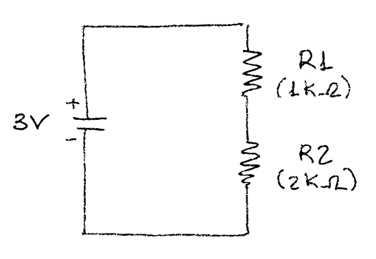
Follow up we have a circuit with an input tension of 3V and two resistors (R1 and R2) in series. That means that the total resistor value is R1 + R2. So lets say R1 has a value of 1KΩ and R2 has a value of 2KΩ, making a total value of 3KΩ. If we look at the picture, we would like to know what is the voltage drop across the first resistor, and what is the voltage drop across the second resistor.
Figure 1. Circuit
The beauty of the problem is that in the end the sum of the voltage across R1 and R2 must be the total voltage we had from the input source. That way we will know whether our calculations were ok or not.
Using Ohm’s law
Now, How do I calculate the voltage across R1 ? Well, short answer is, using Ohm’s law which says that tension equals current times resistance. Here’s the formula and its derivatives:
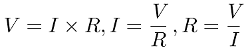
Figure 2. Ohm’s law
In order to use the Ohm’s law in each section, first we need to know the total current of the circuit. Applying the formula we’ve got that:
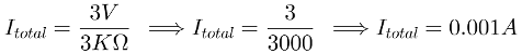
Figure 3. Calculate total current
Then with this value we can apply the Ohm’s law in each section:

Figure 4. Calculate voltage across section 1 and section 2
There’s another formula based on Ohm’s law that I’ve found in this Youtube video, I’ve found it very direct and practical:
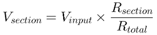
Figure 5. Calculate voltage across section with new formula
As I mentioned earlier, we can now whether this new formula works or not because we should get the same results:
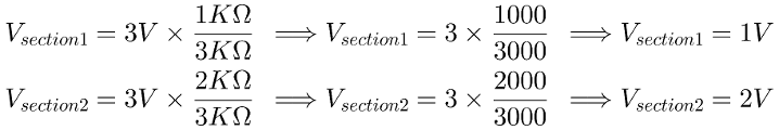
Figure 6. Calculate voltage across section 1 and section 2
Ok, so we can use each section to provide different tension to different components.
Calculating Power dissipation
The resistor choice should take into account the power dissipation. The amount of Watts the resistors are going to dissipate. A low ohm value for your resistors could end up with your resistors burning out in a blink of an eye.
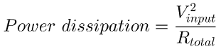
Figure 7. Calculate power dissipation
With this formula in mind, we can calculate the power dissipation of our current resistors:

Figure 8. Current power dissipation
As you can see is almost nothing. Maybe we could even chose a lower resistor value. But imagine we were using resistors adding up 3Ω with an input value of 12V:

Figure 9. catastrophic
Well 72W for such a small circuit is a lot of heat to handle and resistors could end up burning out. So bear in mind to calculate the power dissipation to avoid further problems.
Measuring voltage drop with multimeter
Now that we know how to split the circuit so that we can have different voltage sections, I would like to know how to wire different components requiring different voltage. I drawed a couple of examples showing how I should be using the multimeter to make sure sections have the expected voltage drop.
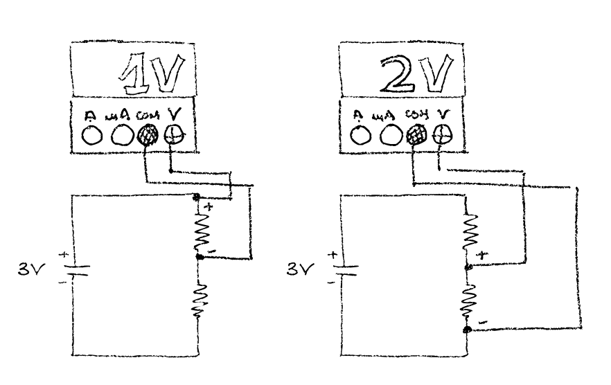
Figure 10. Multimeter measurement
A practical example
I’ve a led which supports maximum tension of 2V and a couple of AA batteries providing 3V to feed the circuit. I’ve put a couple of resistors following the previous circuit layout to extract the 2V required for the led across the second resistor section (2KΩ).
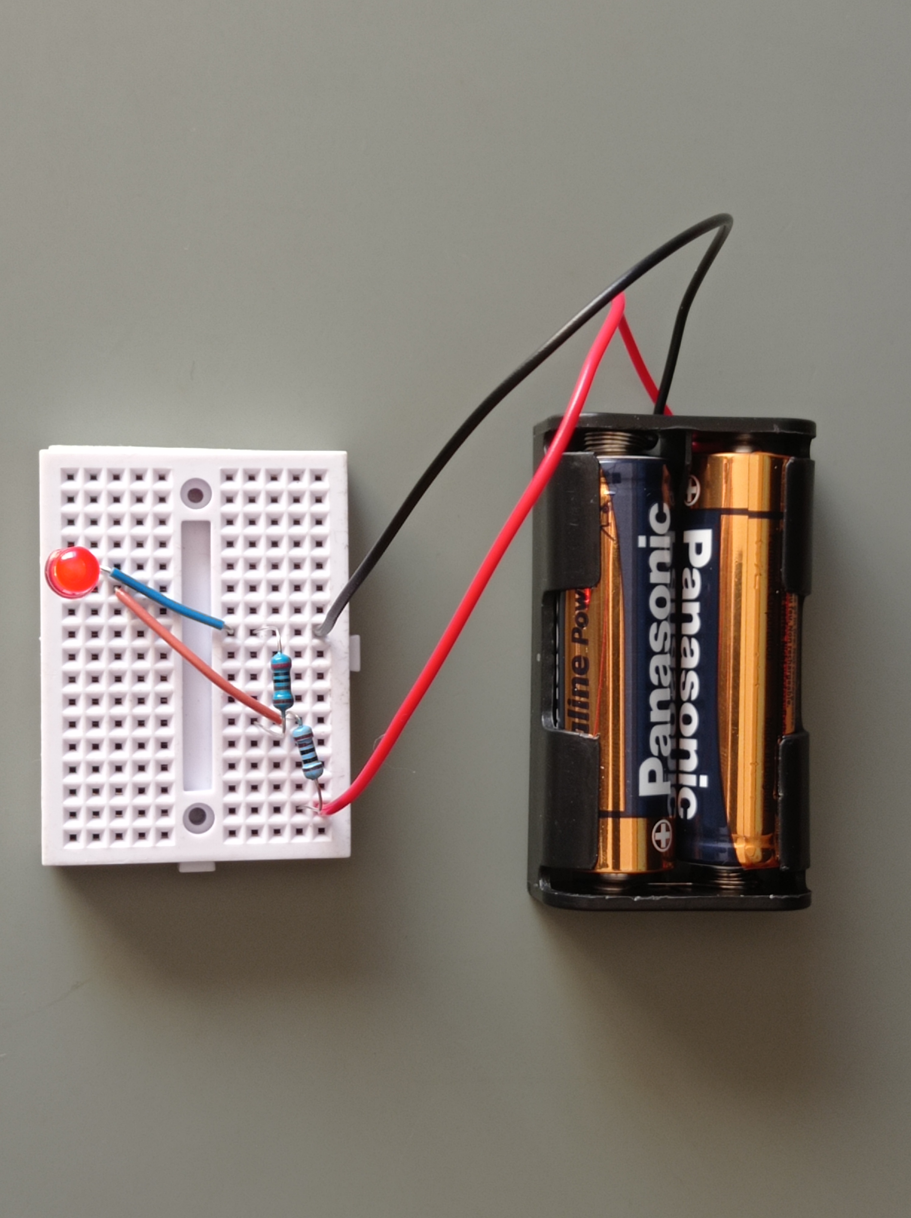
Figure 11. Led circuit